The cone crusher represents a high-precision instrument within any Crushing Plant. Unlike equipment that relies on simple compressive force, the cone crusher operates through exact eccentric rotation and requires tight tolerance management. Premature component failures, such as seized copper bushings, fractured main shafts, or stripped gears, frequently result from incorrect Cone Crusher Installation procedures rather than manufacturing defects. A successful assembly process depends on three technical requirements: absolute cleanliness of components, precise management of thermal and mechanical gaps, and accurate alignment of drive systems. This document provides a technical analysis of the installation procedures for seven core components to prevent equipment failure.
Base Installation: How to Install the Mounting Base and Calibrate Levelness
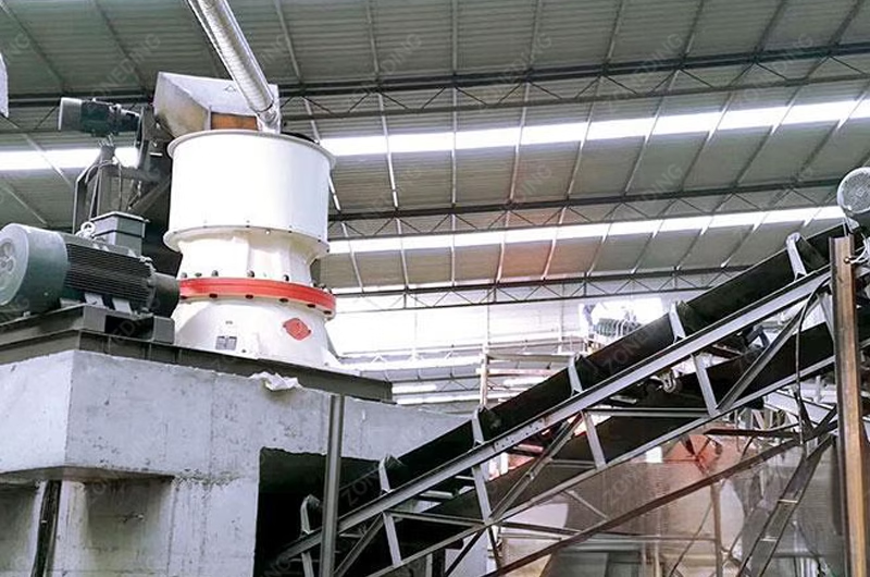
The structural integrity of the crushing operation relies on the stability of the Mounting Base. A cone crusher requires a reinforced concrete foundation calculated to withstand both the static weight of the machine and the dynamic forces generated during operation. During the installation phase, the frame is positioned on the foundation, and the primary technical objective becomes the establishment of absolute levelness. Technicians must use a precision machinist’s level (with a sensitivity of 0.02mm/m) to verify the top machined surface of the frame in both longitudinal and transverse orientations.
Chassis Installation
Base Installation
If the frame deviates from a level plane, the eccentric assembly will operate at a tilted angle. This geometric deviation forces the main shaft to lean against the copper bushings with unequal pressure distribution. Such misalignment creates a localized high-pressure zone that disrupts the formation of the hydrodynamic oil film. This disruption leads to rapid temperature spikes and eventual component seizure. The frame must be leveled within a strict tolerance of 0.1mm per meter. Once this tolerance is achieved, the anchor bolts are tightened to torque specifications, and secondary grouting is applied to immobilize the frame. Effective vibration absorption at the base level is the primary defense against stress fractures in the upper casing.
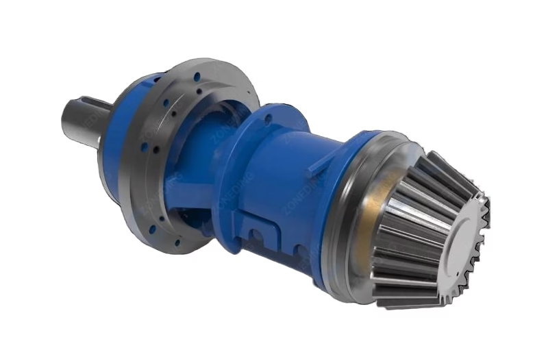
Countershaft Box Installation: Inserting the Shaft and Adjusting Axial Clearance
The installation of the Countershaft Box requires precise alignment of the mechanical transmission system. The pinion gear mounted on the countershaft transfers power to the large eccentric gear, and the interaction between these components is defined by Backlash (side gap) and root clearance. Before the final tightening of the flange bolts, the axial movement (float) of the countershaft must be established. This gap allows for linear thermal expansion of the steel shaft during operation. If this axial gap is insufficient, the shaft will expand as operating temperatures rise, exerting excessive axial load on the bearings and causing premature failure.
Countershaft Box
Countershaft Box
A frequently underestimated critical parameter is the alignment of the external drive pulley. Visual estimation is insufficient for this procedure. The use of a laser alignment tool is necessary to ensure that the crusher sheave and the motor sheave are perfectly parallel and exist on the same vertical plane. If the drive belts exert a diagonal pulling force due to misalignment, that force transfers directly to the countershaft copper bushing. This results in uneven wear patterns and compromises the oil seal integrity, leading to leakage. The Countershaft Box must remain in a neutral position to transmit torque without sustaining detrimental side-loading forces.
Equipment Alignment Standards
Parameter
Tolerance Limit
Technical Consequence of Deviation
Frame Levelness
0.1mm / m
Eccentric bushing inclination, localized wear.
Pulley Parallelism
0.5mm
Countershaft bushing wear, seal failure.
Axial Float
0.8mm – 1.5mm
Bearing seizure due to thermal expansion.
Empty Eccentric Shaft Installation: Fitting the Bushing and Ensuring Gear Mesh
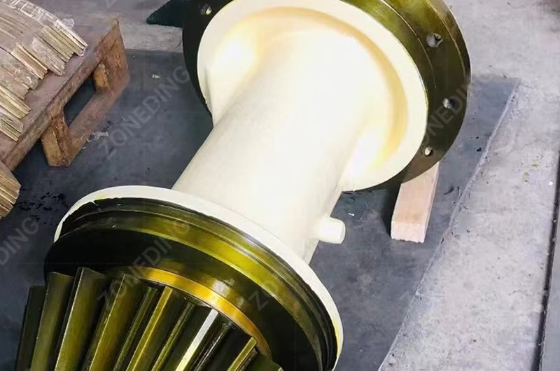
Installing the copper Eccentric Bushing into the main frame or the eccentric steel casting represents a critical assembly step. The application of impact force using sledgehammers or rams is strictly prohibited. Copper is a ductile material, and impact force causes plastic deformation and ovalization of the bushing. An out-of-round bushing prevents the formation of a uniform oil wedge. The standard engineering method for installing these interference-fit components is Cryogenic Assembly. By immersing the bushing in a solution of dry ice and industrial alcohol for a period of 2 to 3 hours, the copper material undergoes thermal contraction, reducing its diameter by 0.1mm to 0.2mm. This thermal contraction allows the bushing to slide into the machined bore under its own weight or with minimal hand pressure. As the component returns to ambient temperature, it expands to form a secure, mathematically circular interference fit. Following the installation of the eccentric assembly, the gear engagement requires verification. Measuring Backlash with a feeler gauge provides only partial data. A Contact Pattern Check using marking compound (Prussian blue or red lead) is mandatory. The compound is applied to the pinion teeth, and the crusher is rotated manually. A compliant contact pattern appears as an ellipse in the center of the tooth flank, occupying 50% to 70% of the tooth length. Concentration of the mark at the edge of the tooth indicates shaft misalignment, which will result in tooth breakage under load.
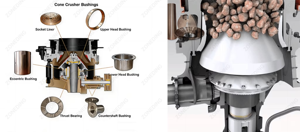
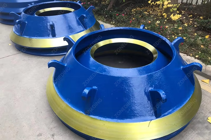
Bowl-Shaped Bearing Installation: Fitting the Socket Liner and Inspecting Contact Area
The Bowl-shaped Bearing (Socket Liner) supports the total mass of the main shaft assembly and the vertical component of the crushing force. It functions as a sliding bearing for the spherical head of the main shaft. The installation of a replacement liner requires a procedure known as Scraping. Installing a machined spare part directly without verification is insufficient for high-load operation. The spherical radius of the liner must correspond exactly to the radius of the main shaft ball to ensure load distribution.
Cone Crusher Bushings
Technicians apply a thin layer of red lead powder to the main shaft head and lower it onto the liner, rotating it partially to transfer the mark to high spots on the bronze. These high spots are then manually removed using a precision scraper. This cycle of marking and scraping is repeated until the contact points form a uniform distribution pattern. The technical standard requires 2 to 3 distinct contact points per square inch across the entire bearing surface. Failure to perform this scraping process results in point-loading, where the entire crushing force is concentrated on a small area. This extreme pressure ruptures the lubrication film, resulting in direct metal-to-metal contact and rapid destruction of the spherical surfaces.
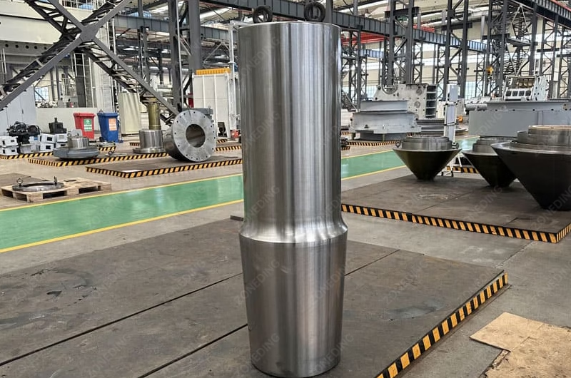
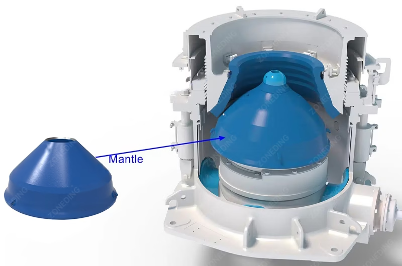
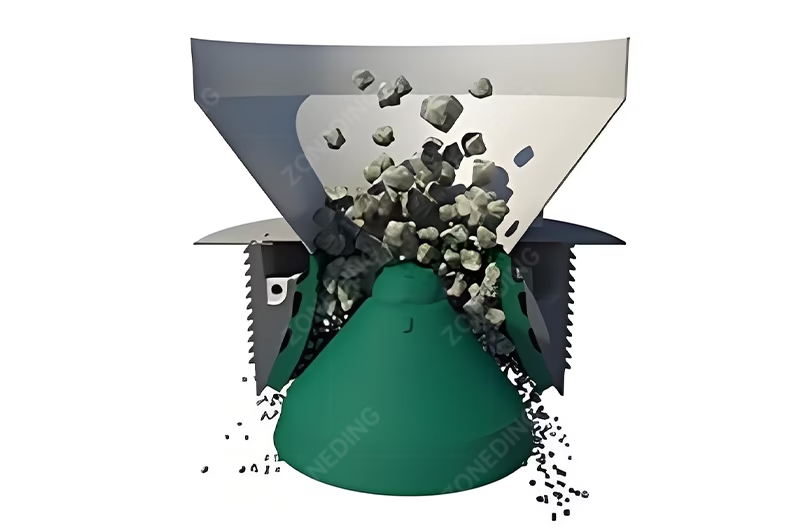
Movable Cone Assembly Installation: Hoisting the Main Shaft and Protecting Liners
The Movable Cone Assembly (Main Shaft Assembly) constitutes the central gyrating component. When replacing the wear liners (Mantle), a backing compound (typically epoxy resin) is poured into the void between the steel liner and the cone body. This compound acts as a shock-absorbing layer. A critical failure mode involves pouring this compound when the metal temperature is low. Before the pouring process begins, the metal surfaces of the cone body and liner must be preheated to a temperature range of 25°C to 30°C.
Main Shaft
Mantle
This preheating process serves two engineering purposes. First, it accelerates the chemical cross-linking of the epoxy resin. Second, and more critically, it evaporates surface condensation. Even microscopic amounts of moisture on the steel will cause the epoxy to foam, creating voids and reducing the compressive strength of the backing layer. Once the liner is secured, the assembly requires careful hoisting. The polished journals of the main shaft must be protected with heavy rubber or wood guarding to prevent contact with lifting chains. A surface scratch on the journal will act as a cutting tool against the eccentric bushing, leading to failure shortly after startup.
Installation Safety Protocols
Surface Protection: The polished journal surfaces must be wrapped in protective material before any lifting chains are attached.
Backing Preparation: Preheating the metal is mandatory to remove moisture and ensure backing compound adhesion.
Hoisting Balance: The assembly must be lifted vertically to prevent the shaft from striking the eccentric bushing during insertion.
Adjustment Ring Installation: Assembling the Ring and Threading the Fixed Cone
The Adjustment Ring supports the fixed cone (Bowl Liner) and facilitates the regulation of the Closed Side Setting (CSS). Before installation, the large diameter saw-tooth threads on both the adjustment ring and the bowl require rigorous cleaning and lubrication. These threads operate under high tension. A coating of molybdenum disulfide paste or a high-pressure lithium-based grease must be applied to all thread surfaces. The presence of abrasive grit or metal shavings in these threads will cause galling (cold welding), rendering the adjustment mechanism inoperable.
Cone Crusher Bowl Liner
Crusher adjustment (CSS)
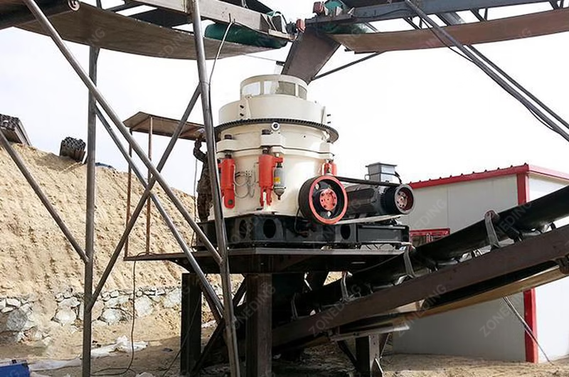
The assembly is lowered onto the main frame, where it engages with the clamping cylinders or spring assemblies. For Mobile Cone Crusher units, the hydraulic motor responsible for rotating the adjustment cap must be checked for proper gear engagement. The ring must rotate without binding during the static test phase. If significant resistance is detected, it indicates thread misalignment or contamination. Forced rotation in this condition will permanently damage the thread profile. The clamping system must be fully depressurized during the adjustment testing to prevent thread damage.
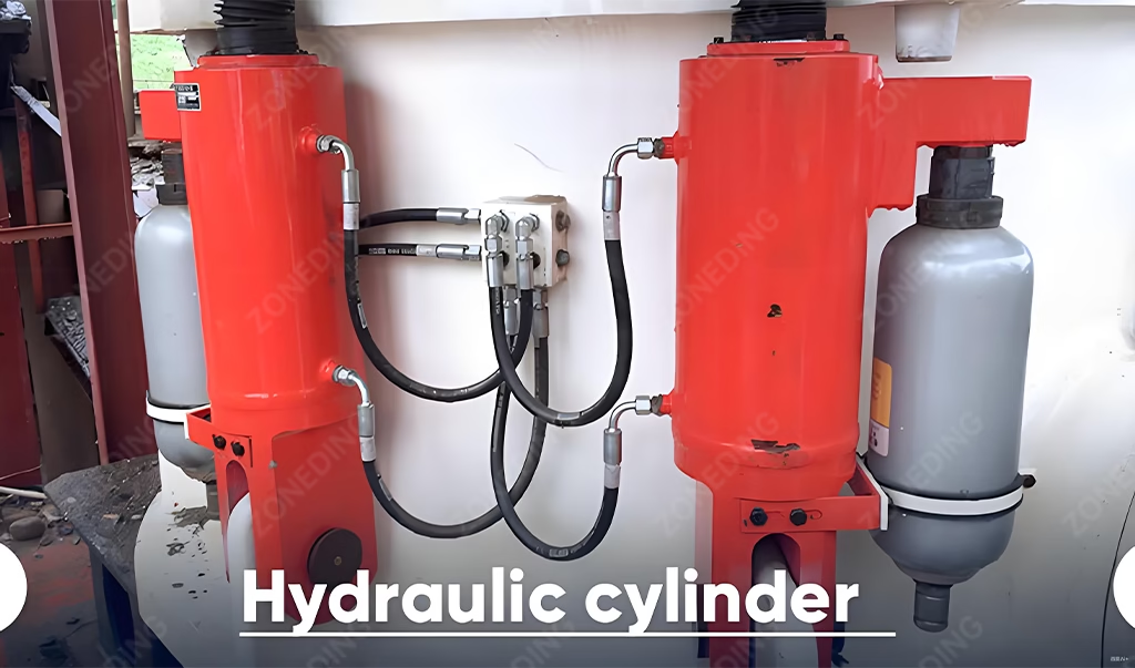
Locking and Hydraulic System: Installing Cylinders and Connecting Lubrication
Modern cone crushers utilize hydraulic systems for clamping, clearing, and adjustment. When installing the locking cylinders, the purging of air from hydraulic lines is essential to maintain constant clamping pressure. However, the Dust Seal system represents the critical barrier for component longevity. This system typically employs a positive pressure blower to inject air into the seal chamber, preventing the ingress of particulate matter.
Installing Cylinders and Connecting Lubrication
The location of the blower air intake determines the effectiveness of this system. If the intake is positioned within the dust zone of the crusher, the blower functions as a pump, forcing abrasive silica dust directly into the oil seal. The intake piping must be routed to a clean, calm air zone or equipped with high-efficiency filtration. The internal air pressure within the seal chamber must exceed the external atmospheric pressure to create an effective aerodynamic barrier. Contamination of the lubrication oil is the primary cause of bearing failure; maintaining oil cleanliness begins with the correct installation of the positive pressure air system.
Test Run Inspection: Conducting No-load Tests and Monitoring Oil Pressure
The final phase of installation is the controlled “Run-in Procedure.” Empirical data suggests that a high percentage of bushing failures occur within the initial 48 hours of operation due to improper run-in. A Beneficiation Equipment system cannot immediately operate at full design capacity following a rebuild. The new copper surfaces possess microscopic asperities that must be smoothed gradually. The procedure commences with a no-load test lasting 2 to 4 hours. During this period, the return oil temperature serves as the primary diagnostic metric. If the return oil temperature exceeds 60°C or exhibits a rapid rate of climb, the operation must cease immediately. This thermal spike indicates insufficient running clearance or assembly misalignment. Following thermal stabilization, material feeding begins at 25% of rated capacity for 4 to 8 hours. The load is subsequently increased to 50%, 75%, and 100% in staged intervals. This gradual loading allows the bearing surfaces to bed in, establishing the geometric conformity required for hydrodynamic lubrication under full load.
Frequently Asked Questions
Q1: Why is the contact pattern check on gears prioritized over backlash measurement? Backlash measurement only quantifies the gap between gear teeth, not the alignment of the shafts. A correct backlash reading can exist even with non-parallel shafts. The contact pattern reveals the load distribution. Edge contact indicates misalignment, which leads to stress concentration and tooth failure, whereas a centered pattern confirms correct alignment. Q2: Is it permissible to reuse existing backing compound when replacing liners? Reuse of backing compound is prohibited. The compound is a thermosetting epoxy that cures into a brittle solid to fill voids and transmit compressive loads. It does not possess melting properties. Old compound must be removed completely to ensure the new liner seats directly against the metal head, preventing movement that fractures the main shaft. Q3: What are the consequences of installing a copper bushing without cryogenic cooling? Installation of a bushing at ambient temperature requires excessive force, typically via sledgehammers or hydraulic rams. This force causes plastic deformation of the soft copper, resulting in an oval-shaped bore. An out-of-round bushing creates high-pressure contact points that disrupt the oil film, leading to localized friction and seizure. Q4: How is the functionality of the dust seal blower verified? Verification involves placing a smoke source or a lightweight strip of paper near the seal gap while the blower is active and the crusher is stationary. The airflow must be directed outward from the machine interior. The absence of outward airflow indicates that the blower is ineffective, allowing dust to be drawn into the lubrication system. Q5: What is the correct response to a rapid oil temperature spike during the initial run? The equipment must be shut down immediately. Attempts to cool the machine with external fans while continuing operation are prohibited. A temperature spike indicates that friction generation exceeds the heat dissipation capacity of the oil, caused by tight clearances or misalignment. Disassembly and inspection of surfaces are required.
About ZONEDING
ZONEDING Machine manufactures Cone Crushers and mineral processing equipment designed for the global mining sector. The company focuses on the production of high-precision crushing machinery that prioritizes ease of maintenance and operational durability. ZONEDING provides technical guidance to ensure optimal plant performance and equipment longevity.
Choosing mobile crushing equipment determines project setup speed and long-term operating costs. Many buyers only look at the transport method. They ignore the hidden costs of site preparation and energy consumption. This guide shows the real diff...
Cone crushers are among the most widely used machines in the aggregate, mining, and quarry industries. They are especially popular for processing hard and abrasive materials such as granite, basalt, river stone, and iron ore. However, many buyers ...
Learn the complete lithium ore crushing and processing flow, including spodumene beneficiation, equipment selection, plant costs, recovery optimization, and ROI analysis.
I have spent 50 years in the mining and recycling industry. I have seen people turn piles of trash into mountains of cash. But I have also seen many people lose everything because they bought the wrong machine. In 2026, urban recycling is a gold m...
We use cookies to ensure that we give you the best experience on our website. If you continue to use this site we will assume that you are happy with it.
Privacy Policy
Send us a message
We would love to hear from you
Submit your question and our team will respond to the email provided as soon as possible.
 Zoneding Machine