The feeding assembly regulates the input rate of ore, water, and circulating load into the grinding chamber. Efficiency in ball mill operation depends on the compatibility between the feeding device and the process flow requirements. An incorrect selection restricts throughput and causes mechanical instability. This article analyzes the technical specifications, operational mechanisms, and application scenarios for Chute, Drum, and Combined feeders to facilitate optimal plant design.
Why Does the Feeding Method Determine Capacity and Efficiency?
The trunnion inlet of a Ball Mill functions as the convergence point for multiple material streams. This restricted passage must accommodate crushed fresh ore, process water, and the circulating load returned from classification equipment. In closed-circuit grinding operations, the volume of returned sand frequently exceeds the fresh feed volume by 300% to 500%. The feeding device acts as a flow regulator. A feeder with insufficient hydraulic capacity causes material accumulation at the inlet. This accumulation results in “back-spill,” where abrasive slurry ejects backward through the seal gap, contaminating the main bearings. To prevent this, operators often reduce the fresh feed rate, which directly lowers the overall plant production. Consequently, the selection of the feeding method dictates the maximum hydraulic limit of the grinding circuit.
Chute Feeder: The Economic Choice for High-Drop Configurations
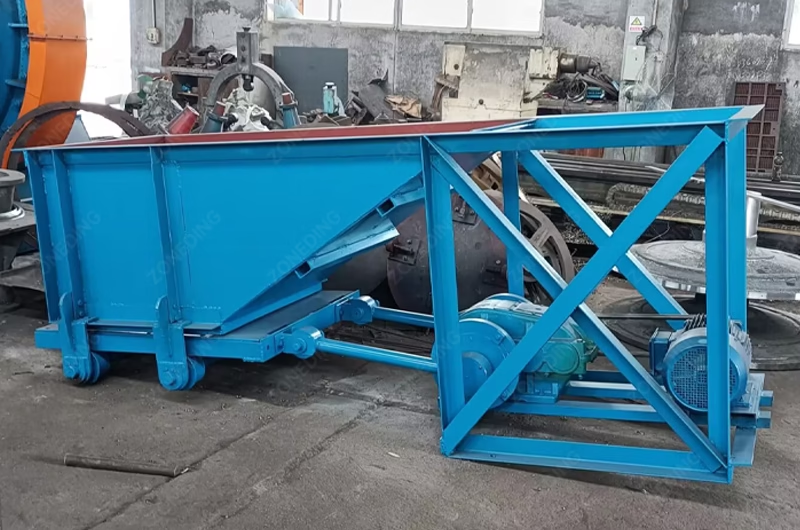
The Chute Feeder, technically referred to as a Spout Feeder, represents the simplest mechanical design for material introduction. The structure consists of a fixed, inclined conduit manufactured from steel plate. Gravity serves as the sole driving force for material transport. The ore slides down the incline and enters the hollow shaft of the trunnion directly.
Operational Mechanics and Limitations
Engineering designs utilize the chute feeder primarily for its absence of moving parts. The device requires no external drive mechanism and consumes no electrical energy. Manufacturing costs remain lower compared to rotating alternatives. Maintenance procedures involve liner inspection and replacement. However, reliance on gravity imposes specific limitations. The static nature of the chute generates no positive pressure. In wet grinding applications with high circulating loads, the internal slurry level within the mill may rise. Without positive displacement force, the gravity-fed material cannot overcome the internal pressure of the mill pulp. This limitation renders the chute feeder unsuitable for heavy-duty closed-circuit operations where the Spiral Classifier returns large volumes of sand.
Wear Patterns and Material Selection
The continuous sliding of abrasive ore creates concentrated wear zones within the chute. The impact focuses on the bottom plate and the transition point entering the trunnion liner. Standard carbon steel liners degrade rapidly under these conditions. Optimized installations employ wear-resistant materials such as high-alumina ceramics or molded rubber liners. These materials offer superior resistance to sliding abrasion compared to metallic liners. Regular monitoring of the internal lining prevents the chute casing from perforation, which protects the foundation from slurry leakage.
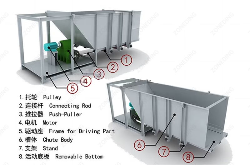
Chute Feeder
chute feeder structure
Application Scenarios for Chute Feeders
Open Circuit Grinding: Operations where material passes through the mill once without return.
Dry Grinding: Processes involving dry powders (cement, silica flour) where moisture does not impede flow.
High Elevation Layouts: Plants where the feeding conveyor or bin sits significantly higher than the mill inlet, providing substantial gravitational potential energy.
Drum Feeder: The Standard for Closed-Circuit Efficiency
The Drum Feeder constitutes the standard configuration for the majority of wet grinding concentrators. The device consists of a cylindrical casing bolted directly to the trunnion of the mill. The internal structure functions based on the Archimedes screw principle.
Positive Displacement Mechanism
The drum rotates synchronously with the ball mill. Internal spiral blades collect the mixture of ore and water from the intake opening. As the drum turns, the spirals physically push the material forward into the grinding chamber. Unlike the passive chute feeder, the drum feeder generates positive displacement force. This mechanism forces the slurry into the mill regardless of the internal pulp level.
Handling High Circulating Loads
Closed-circuit grinding systems require the processing of circulating loads significantly larger than the fresh feed rate. The drum feeder accommodates this requirement effectively. The pumping action manages the high volume of coarse sand returned from hydrocyclones or classifiers without backing up. The enclosed design of the drum also minimizes the risk of slurry splashing onto the trunnion bearings, providing a cleaner operating environment.
Structural Considerations
Drum feeders exist in single-spiral and double-spiral configurations. Double-spiral designs offer higher capacity and smoother flow but increase the weight on the trunnion. The connection between the drum and the trunnion requires precise alignment. Eccentric rotation causes vibration, which accelerates wear on the main bearings and the feeder bolts.
Feature
Chute Feeder
Drum Feeder
Operational Consequence
Transport Force
Gravity
Mechanical Spiral
Drum functions regardless of mill fill level.
Circuit Suitability
Open Circuit / Dry
Closed Circuit
Drum manages high return volumes.
Maintenance Focus
Liner Wear
Bolt Torque / Spiral Wear
Loose bolts in drums cause catastrophic blockages.
Installation Cost
Low
Moderate
Drum provides higher process stability.
Combined Feeder: Solutions for Low-Level Plant Layouts
The Combined Feeder, often termed a Scoop Feeder, addresses specific constraints regarding plant elevation. In certain plant designs, particularly older installations or retrofits, the discharge point of the classification equipment sits at or below the centerline of the ball mill. Gravity transport becomes impossible in these scenarios.
The Lifting and Feeding Mechanism
The design incorporates a rotating scoop arm attached to the drum. This scoop functions similarly to a water wheel. With each revolution of the mill, the scoop dips into a feed box or launder located below the mill axis. The scoop excavates the sedimented pulp and elevates the material to the center. Once elevated, the internal spirals within the drum section guide the material into the trunnion. This self-priming capability eliminates the requirement for auxiliary slurry pumps to lift the return sand.
Mechanical Disadvantages and Stresses
Although the combined feeder solves elevation issues, the design introduces mechanical disadvantages. The assembly adds significant mass and bulk to the rotating body. This overhanging weight increases the bending moment on the mill head and trunnion. Furthermore, the intermittent impact of the scoop entering the sand pile generates cyclic shock loads. These shocks transfer through the mill body to the ring gear and pinion, potentially accelerating gear fatigue. Modern large-scale Gold Processing Plant designs typically avoid scoop feeders. Engineers prefer installing slurry pumps to lift the return material to a standard drum feeder or a high-level box. This approach isolates the mill from the shock loads associated with the scooping action.
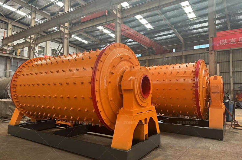
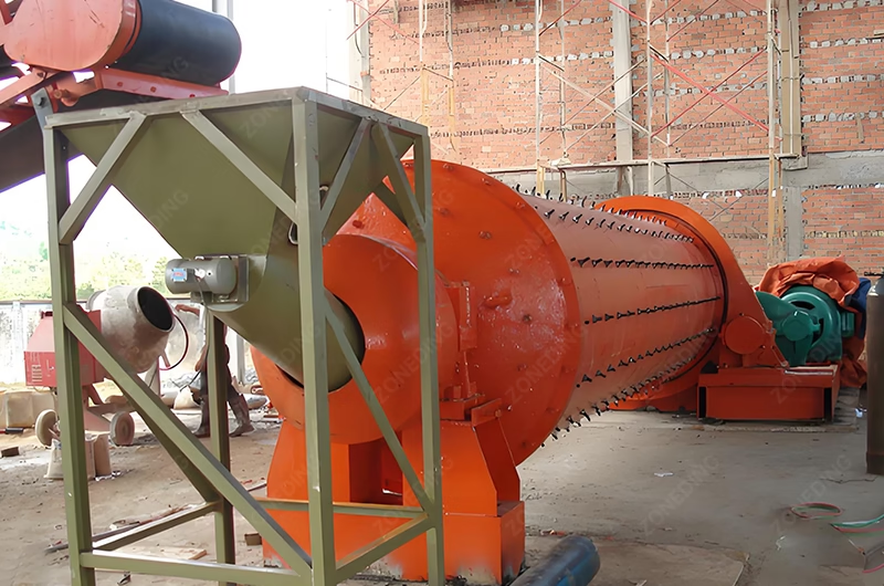
Ball Mill
Design of Ball Mill Feeding Method
Wear Component Maintenance
The leading edge of the scoop endures extreme abrasion during the digging phase. Manufacturers utilize replaceable wear tips casting from high-chrome alloy or manganese steel. Failure to replace worn tips reduces the effective volume of the scoop. A reduction in scoop capacity leads to sand accumulation in the return launder, which eventually blocks the discharge of the classifier.
Selection Guide: Engineering Criteria for Feeder Specification
The selection process relies on three primary variables: Circuit Type, Plant Layout, and Material Characteristics.
1. Analysis of Circuit Type
Closed-circuit operations necessitate the use of Drum Feeders. The positive displacement action ensures consistent flow despite fluctuations in the circulating load. Open-circuit systems function adequately with Chute Feeders, provided the feed rate remains controlled.
2. Evaluation of Plant Elevation
The relative height difference between the classifier discharge and the mill inlet determines the feasibility of gravity flow.
Classifier Higher than Mill: Gravity flow allows for Chute or Drum feeders.
Classifier Lower than Mill: The system requires a Combined Feeder (Scoop) or an external pumping system.
3. Material Moisture Content
Dry Grinding: Operations almost exclusively employ Chute Feeders equipped with dust containment seals.
Wet Grinding: Processes utilize Drum or Scoop feeders to manage the fluid dynamics of the slurry.
Maintenance of the Feeding Assembly
The interface between the stationary supply pipe and the rotating feeder represents a critical maintenance zone. Failure in this area leads to rapid equipment degradation.
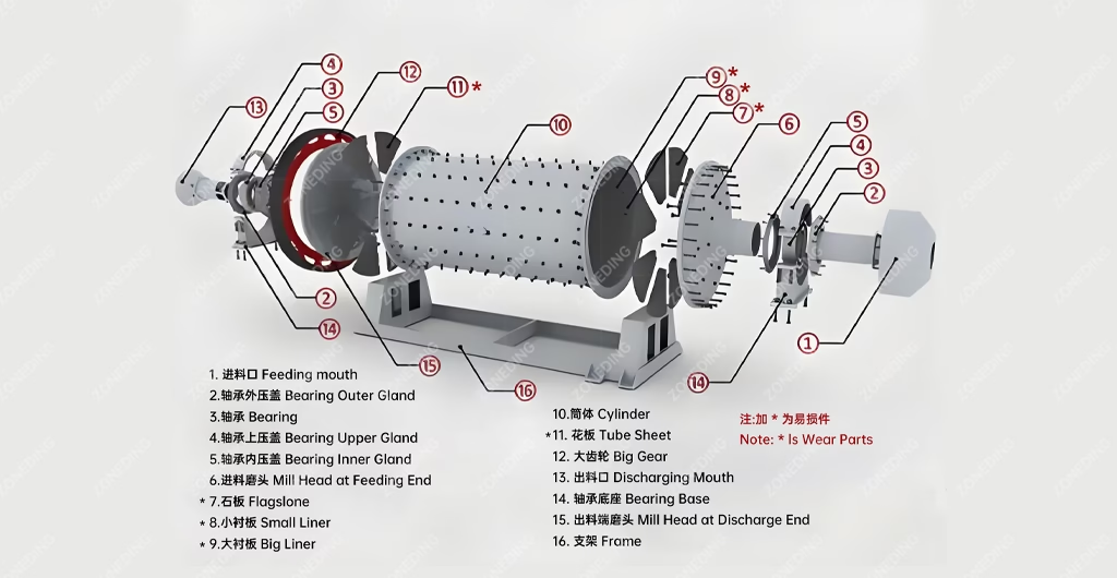
Ball mill structure
Trunnion Seal Integrity
The seal located between the feeder and the hollow shaft requires strict monitoring. Leakage at this junction forces abrasive slurry into the gap between the trunnion and the Main Bearing. Silica particles present in the slurry disrupt the oil film and scour the soft Babbitt alloy of the bearing. High-reliability installations utilize multi-pass labyrinth seals and require precise O-ring installation during assembly.
Water Injection Configuration
The feeding process involves the introduction of process water. The placement of the water injection pipe influences material flow. Operators should direct high-pressure wash water in the direction of the flow. This stream acts as a lubricant, accelerating the ore through the trunnion throat. Insufficient water pressure causes sticky ores to accumulate in the inlet, leading to blockages and material rejection.
Upstream Feed Stability
The performance of the feeder depends on the stability of the incoming supply. A ball mill operates most efficiently with a constant feed rate. Feeding directly from a crusher discharge conveyor often results in fluctuations. The installation of a fine ore bin acts as a buffer. A Vibrating Feeder positioned under the bin ensures the mill receives a precise, constant tonnage. This stability maintains the grinding density and prevents liner damage associated with running the mill empty.
2026 Trends in Feeding Technology
Recent developments in mineral processing technology focus on wear resistance and flow simulation.
Advanced Wear Materials
The industry is shifting towards composite liners for feeders. These liners combine the impact resistance of steel with the abrasion resistance of ceramics. The extended lifespan of these materials reduces the frequency of maintenance shutdowns.
DEM Simulation for Design
Manufacturers now use Discrete Element Method (DEM) software to simulate material flow through the feeder. This analysis allows for the optimization of spiral angles and scoop shapes to maximize throughput and minimize wear before fabrication.
Smart Monitoring
Integration of vibration sensors on the feeder casing helps detect loose bolts or liner detachment early. This condition monitoring capability prevents catastrophic failures and unplanned downtime.
FAQs
Q1: Can a standard Chute Feeder operate effectively in a closed-circuit grinding system? Engineering standards generally advise against this configuration. Chute feeders utilize gravity alone and lack the positive displacement pressure required to overcome the internal slurry level. High circulating loads in closed circuits typically cause material backup and spillage at the inlet when using a chute feeder.
Q2: What is the primary cause of mechanical failure in Drum Feeders? The loosening of connecting bolts represents the most frequent failure mode. Vibration from the mill operation causes the bolts securing the drum to the trunnion to lose torque over time. This looseness damages the flange surface and can lead to liner detachment inside the drum, blocking the material flow.
Q3: How does the choice of feeder affect the Main Bearing life? The feeder type impacts the bearing load and seal integrity. Combined (Scoop) feeders add significant overhanging weight and cyclic impact loads, potentially accelerating bearing fatigue. Furthermore, a poor seal between any feeder and the hollow shaft allows abrasive slurry to contaminate the bearing lubrication, leading to rapid Babbitt metal failure.
Q4: Is retrofitting an existing mill from a Scoop Feeder to a Drum Feeder possible? Conversion is feasible and often recommended for modernization. Replacing a Scoop Feeder with a Drum Feeder reduces the mechanical load on the mill drive. However, the plant layout must accommodate an external slurry pump to lift the return sand, as the Drum Feeder lacks the self-lifting capability of the Scoop.
Q5: What material offers the best longevity for Scoop Feeder tips? High manganese steel (Mn13Cr2) or high chromium alloy steel provides optimal resistance for scoop tips. These components endure extreme impact and abrasion while digging into the sand pile. Regular replacement of the tips preserves the structural integrity of the main scoop body and maintains the volumetric lifting capacity.
Q6: Why does slurry discharge from the feed inlet during operation? “Back-spill” or “vomiting” usually indicates a hydraulic restriction. Common causes include a blockage inside the feeder spirals, insufficient water pressure to flush the material, or a feed rate exceeding the flow capacity of the trunnion screw.
About ZONEDING
ZONEDING manufactures a comprehensive range of mineral processing equipment, including heavy-duty ball mills and optimized feeding systems. The company provides engineering support for plant layout design, circuit optimization, and equipment customization. The product portfolio includes crushing equipment, grinding mills, and flotation machines tailored to specific mining requirements. Contact the technical team for detailed specifications regarding ball mill feeders and circuit design.
Aggregate plants face challenges with hard rock processing daily. Cone crushers in the aggregates industry solve this exact problem efficiently. High-grade construction projects require perfectly shaped stones constantly. These machines handle ext...
Many quarry operators spend months comparing crusher models, motor power, and production capacity. However, very few spend the same amount of time evaluating the jaw plates that actually perform the crushing. That oversight can become surprisingly...
Stop fine gold loss by using a combination of high-energy washing and centrifugal separation. Most mines lose 30% of their gold because they only use simple sluice boxes. Successful alluvial gold processing technology requires a multi-st...
I have spent 50 years in the mining and recycling industry. I have seen people turn piles of trash into mountains of cash. But I have also seen many people lose everything because they bought the wrong machine. In 2026, urban recycling is a gold m...
We use cookies to ensure that we give you the best experience on our website. If you continue to use this site we will assume that you are happy with it.
Privacy Policy
Send us a message
We would love to hear from you
Submit your question and our team will respond to the email provided as soon as possible.
 Zoneding Machine