Understanding the main components of flotation machine is mandatory for maximizing profits in mineral processing plants. A flotation cell acts as a highly precise separation instrument. The internal mechanical structure dictates the exact slurry suspension efficiency and aeration quality. Small changes in internal gaps or tank designs cause massive fluctuations in daily metal output. This guide explains how specific structural elements directly improve flotation recovery rate and prevent catastrophic equipment failures.
Impeller-Stator Clearance: Impact on Flotation Aeration
The flotation machine impeller and stator serve as the absolute heart of the entire mineral separation process. These main components of flotation machine mix the heavy mineral slurry and cut the incoming air into microscopic bubbles. Mechanical agitation cells require a very strict clearance gap between the spinning impeller and the stationary stator. This gap usually measures between 8 and 12 millimeters when the machine leaves the factory. The exact measurement completely determines the slurry suspension efficiency. The spinning blades must shear the air perfectly to create tiny, uniform bubbles. Micro-bubbles provide massive surface area for valuable minerals to attach. The metal or rubber parts wear down constantly during continuous daily operation. The clearance gap grows larger over time. A wider gap destroys the mechanical shearing action entirely. The machine stops producing micro-bubbles and starts creating giant, unstable air pockets.
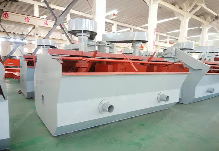
Flotation Machine
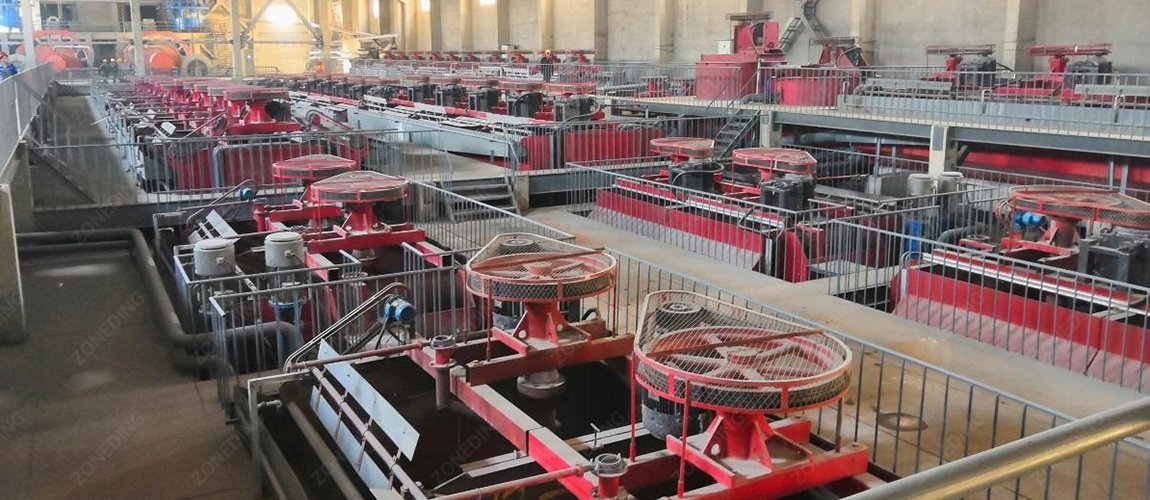
Flotation Site
Giant bubbles have far too much lifting force for delicate mineral separation. They pull heavy, useless gangue rock straight up to the surface. This immediately ruins the final concentrate grade. The large bubbles also pop very easily upon reaching the surface layer. Valuable minerals lose their lifting support and drop straight back down into the mud. Operating the plant with severely worn parts causes massive hidden financial losses. The daily metal output drops slowly and silently. Many operators simply increase the chemical dosage to fix the falling recovery rates. This wastes thousands of dollars on expensive reagents. The only true solution involves shutting the machine down and restoring the factory clearance gap. Replacing these internal parts strictly on schedule prevents invisible drops in daily mineral recovery.
Setting the Optimal Operating Clearances
The maintenance team must measure the impeller gap during every single scheduled shutdown. The measurement requires a specialized feeler gauge or a simple lead block test. Uneven wear across the stator indicates an imbalanced main shaft. This imbalance requires immediate correction before it destroys the main bearings.
Component Issue
Physical Effect
Impact on Mineral Recovery
Gap Too Small
Extreme motor load
High energy cost, motor burnouts
Gap Too Wide
Giant unstable bubbles
Low concentrate grade, drop-back
Uneven Wear
Slurry vortex changes
Incomplete suspension, sanding up
Practical Maintenance Steps for Impeller Systems
Measure Monthly: Check the gap between the impeller and stator with a lead block every month.
Check Balance: Inspect the main shaft for vibration to ensure the impeller spins perfectly level.
Record Wear: Log the wear measurements in a database to predict exact replacement dates accurately.
How to Choose Materials Based on Slurry Abrasiveness?
Choosing the absolutely correct material for internal components directly dictates the wear parts lifespan of flotation cell. Plant managers constantly face choices between natural rubber, polyurethane, and high chrome cast iron alloys. Rubber offers extraordinary natural elasticity. It absorbs massive impacts from sharp, abrasive particles perfectly. Plants processing very coarse quartz or sharp gold veins always prefer natural rubber stators. Rubber simply bounces the sharp rocks away without taking permanent surface damage. The rubber material lasts a very long time in pure physical abrasion environments. This makes natural rubber the standard choice for most primary grinding and coarse separation stages. However, rubber fails completely in certain harsh chemical environments. Fine muds often require high doses of strong chemical reagents. These chemicals include diesel oil, kerosene, or highly aggressive collectors. These petroleum-based chemicals attack natural rubber instantly. The rubber absorbs the oil, swells up massively, and loses all its mechanical strength. The spinning forces then tear the swollen rubber into small pieces. Polyurethane flotation parts solve this exact chemical breakdown problem. Polyurethane resists harsh chemical degradation completely. It handles ultra-fine slurries and aggressive reagents without swelling or cracking. High chrome iron serves best in extreme high-wear environments with very large, heavy particles. Chrome parts handle the sheer physical scratching of heavy iron ores. Selecting the wrong material easily triples the annual maintenance budget. Teams handling mineral processing spare parts procurement must analyze the exact slurry chemistry before buying.
How Flotation Design Prevents Short-Circuiting and Sanding Up?
Flotation equipment structure dictates slurry flow and processing efficiency. While deep tanks save space and motor costs, they fail with coarse particles; violent turbulence during the long ascent detaches heavy minerals from bubbles. Therefore, processing coarse materials requires shallow tanks for a shorter transit.
Another structural issue is “short-circuiting,” where mud exits without mixing with bubbles. Effective designs solve this using internal baffles to force slurry directly through the impeller zone. Additionally, “sanding up” occurs when heavy rocks settle in square tank corners, forming solid dead zones. Modern tanks prevent this by utilizing U-shaped or cylindrical bottoms, eliminating dead corners and keeping the slurry in continuous motion.
Tank Design Selection Criteria
The selection between tank types depends completely on the mineral liberation size. The grinding circuit dictates the particle size. The particle size dictates the tank depth. This simple rule prevents massive design failures.
Tank Structure
Best Application
Major Weakness
Shallow Square
Coarse heavy particles
Takes up huge floor space
Deep Cylindrical
Fine light particles
Fails to float coarse minerals
U-Shaped Bottom
High density slurries
Manufacturing costs run higher
Operational Tank Management Rules
Check Corners: Inspect the tank corners with a long rod daily to check for hard sand buildup.
Adjust Baffles: Move the internal weir plates to change the exact slurry retention time.
Match Grinding: Ensure the Ball Mills produce the correct particle size for the chosen tank depth.
External Air Supply vs. Self-Aspirating Aeration and Agitation Mechanism?
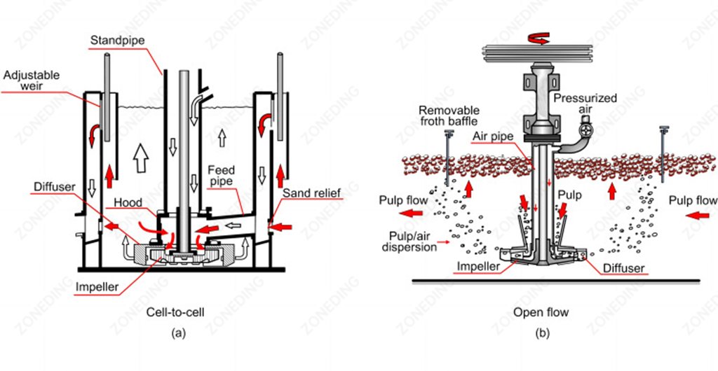
The aeration and agitation mechanism controls the exact amount of air entering the mud. Two completely different philosophies exist for introducing this air. Self-aspirating machines act like giant vacuum cleaners. The spinning impeller creates a strong negative pressure zone at the bottom of the shaft. This vacuum sucks fresh air straight down a hollow standpipe. The machine pulls exactly the amount of air it needs based on the spinning speed. This design is incredibly simple. It requires no external air compressors or complex air piping. Operators just turn the main motor on, and the machine breathes automatically. It works perfectly for small to medium-sized processing plants.
Schematic Diagram of Two Typical Flotation Cell Configurations
External air supply machines, also known as forced-air cells, operate differently. These machines use massive external blower fans. The blowers push compressed air forcefully down into the tank bottom. The spinning impeller only mixes the mud; it does not need to create a vacuum. This separation of duties provides ultimate control. Operators can turn a valve to increase the air volume while keeping the mixing speed exactly the same. This precise control prevents the mud from boiling. Boiling happens when too much air enters a shallow tank. The surface erupts violently, destroying the delicate froth layer. Forced-air systems allow operators to fine-tune the bubble density perfectly. Modern large-scale Copper Processing Plants strictly use forced-air systems to achieve maximum metallurgical stability.
How Do Draft Tubes and False Bottoms Play a Key Role in Internal Circulation?
Maintaining aggressive internal slurry circulation prevents catastrophic equipment damage. Heavy mineral slurries want to settle at the bottom naturally. If the slurry settles, it packs tightly around the impeller. When the motor tries to start, the locked impeller snaps the main steel shaft instantly. To prevent this, engineers install draft tubes and false bottoms. The draft tube acts as a vertical chimney surrounding the main spinning shaft. It connects the upper layers of the liquid directly to the bottom impeller zone. As the impeller spins, it acts like a pump. It pulls light, airy slurry down through the draft tube and blasts it out across the tank bottom. The false bottom sits just above the actual steel floor of the tank. It features specific directional holes and channels. The blasted slurry hits the false bottom and flows rapidly toward the outer walls. The slurry hits the curved walls, travels straight up, and enters the top of the draft tube again. This creates a massive, continuous vertical loop. The entire tank volume turns over multiple times per minute. Heavy particles can never settle because the upward flow constantly lifts them. This aggressive circulation also forces the unfloated minerals to pass through the bubble-generation zone dozens of times. Multiple passes guarantee that every single valuable grain eventually hits a bubble. Using a draft tube design drastically improves the final output in Gold Flotation circuits.
Circulation Component Details
Draft tubes require careful alignment during installation. A crooked tube causes uneven flow and violent shaft vibration. The false bottom plates must bolt down tightly to prevent vibration wear.
Component
Main Function
Operational Benefit
Draft Tube
Pulls top slurry downward
Increases particle-bubble collision rates
False Bottom
Directs bottom outward flow
Completely stops heavy sand accumulation
Stator Blades
Stops slurry spinning motion
Converts rotational energy into upward lift
Best Practices for Slurry Flow
Clear the Tube: Flush the central draft tube with high-pressure water before starting the main motor.
Check Plate Bolts: Tighten all false bottom securing bolts during every scheduled maintenance stop.
Monitor Amperage: Watch the motor power draw. Low amperage means the draft tube is likely clogged.
2026 Latest Flotation Machine Developments and Trends
The mineral processing industry in 2026 focuses heavily on artificial intelligence and automated component monitoring. Plants no longer rely on visual inspections to guess the wear parts lifespan of flotation cell components. Modern machines feature internal acoustic sensors mounted directly on the stator structures. These sensors listen to the sound of the slurry hitting the rubber. As the rubber wears thin, the acoustic frequency changes. The central computer analyzes this sound and predicts the exact day the part will fail. This allows the mineral processing spare parts procurement team to order replacements perfectly on time. Another major trend involves extreme ultra-fine particle flotation. Traditional machines fail to capture particles smaller than 10 microns. The industry now utilizes specialized high-shear cavitation tubes before the main flotation tanks. These tubes force the slurry through microscopic nozzles. The massive pressure drop causes dissolved air to instantly form nano-bubbles directly on the surface of the ultra-fine gold or copper particles. This breakthrough technology pushes overall recovery rates past 95% in ores that were previously considered impossible to process.
Automated Froth Cameras: Vision systems analyze bubble color and size to automatically adjust the external air valves.
Frequently Asked Questions
Question 1: What is the normal wear parts lifespan of flotation cell impellers? The lifespan depends entirely on the slurry abrasiveness and rotating speed. Rubber impellers in fine, non-corrosive slurries often last 12 to 18 months. High-speed impellers in sharp, coarse quartz slurries might require replacement every 3 to 4 months. Question 2: Why does the froth surface look like boiling water? Boiling occurs when the external forced-air volume exceeds the tank’s handling capacity. The excess air forms massive bubbles that erupt violently at the surface. Closing the main air supply valve slowly stops the boiling effect. Question 3: Does a deeper tank always improve flotation recovery rate? No. Deep tanks provide longer residence time for fine particles. However, deep tanks cause severe drop-back for heavy, coarse particles. Coarse minerals require shallow tanks to minimize the travel distance to the froth surface. Question 4: Can polyurethane flotation parts replace rubber in all machines? Polyurethane excels in chemical-heavy and fine-mud environments where rubber swells and degrades. However, polyurethane is harder and handles direct sharp-rock impact poorly compared to natural rubber. Match the material to the exact ore type.
About ZONEDING
ZONEDING has manufactured highly precise mineral processing equipment since 2004. The factory produces heavy-duty flotation machines, crushers, and ball mills designed for the harshest global mining environments. The engineering team focuses strictly on exact internal tolerances and premium wear materials to maximize daily metal recovery. Reliable equipment architecture ensures continuous, profitable operation for facilities worldwide. Contact the engineering team to discuss specific tank designs and precise wear part materials for upcoming projects.
When a client asks about the , they usually expect a simple price for tanks, pumps, and conveyors. However, the equipment quote is only the tip of the iceberg. In my experience, the equipment represents only 30% to 40% of the total investment. The...
One of the first questions buyers ask before purchasing a cone crusher is: How many tons per hour can a cone crusher produce? The answer is not as simple as reading a specification sheet. Many operators discover that actual production differs sign...
For many mining companies, iron ore tailings are considered a waste problem. However, rising environmental regulations and increasing demand for construction materials have changed the situation. Today, many mines are discovering that: Iron ore ta...
South America continues to invest heavily in mining, highways, hydropower, and infrastructure, creating strong demand for mobile crushing equipment. Among all mobile crushers, the mobile jaw crusher remains the preferred choice for prima...
We use cookies to ensure that we give you the best experience on our website. If you continue to use this site we will assume that you are happy with it.
Privacy Policy
Send us a message
We would love to hear from you
Submit your question and our team will respond to the email provided as soon as possible.
 Zoneding Machine