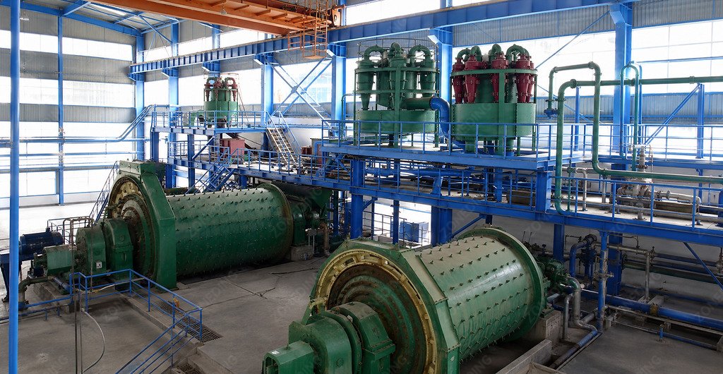
A ball mill and hydrocyclone circuit is a common closed grinding system in mineral processing. Yet good performance depends on more than connecting a mill to a cyclone. Grinding energy, slurry delivery, classification, and circulating load must remain in balance.
When they fall out of balance, a plant may experience unstable P80, coarse overflow, cyclone roping, lower fresh-feed capacity, overgrinding, and higher energy use.
The correct approach is to design and operate the ball mill, sump, pump, hydrocyclone, water system, and downstream process as one connected circuit.
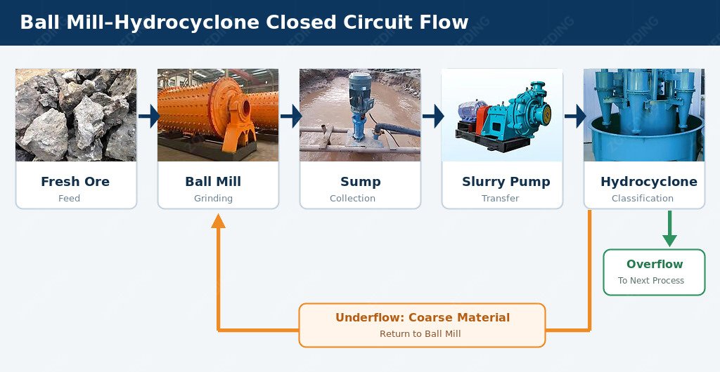
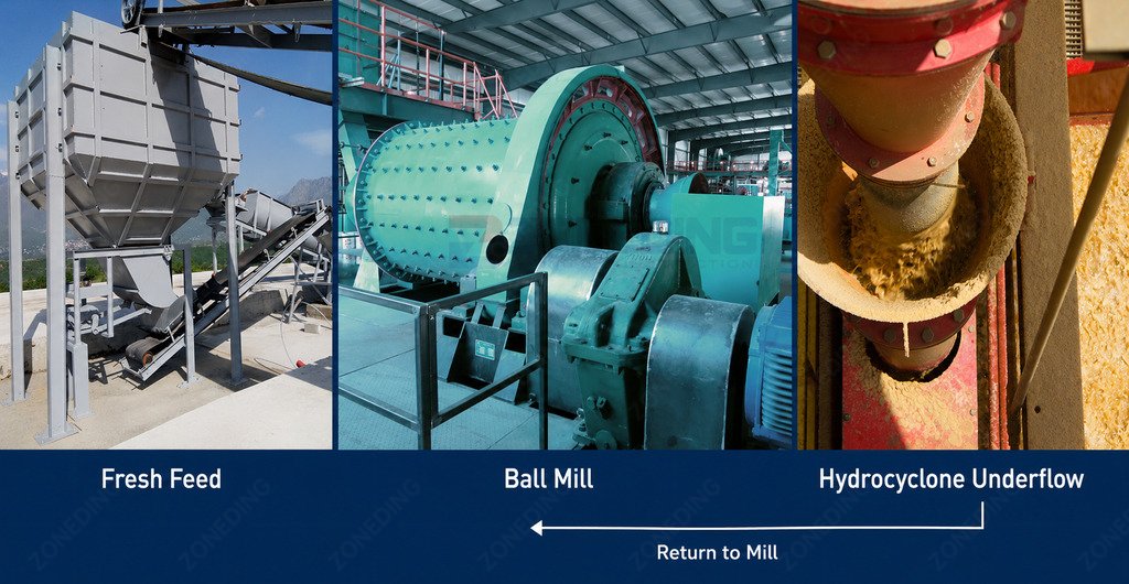
The hydrocyclone then divides the slurry into two streams:
Overflow → Qualified Fine Product → Downstream Process
Underflow → Coarser Material → Return to Ball Mill
Ball mill sump slurry pump and hydrocyclone closed circuit flow
The ball mill reduces particle size through impact and abrasion. The hydrocyclone does not grind the ore. Instead, it determines which particles can leave the circuit and which return for further grinding.
Coarse overflow may provide inadequate mineral liberation. Excessive fine return makes the mill consume power without equivalent useful production.
In many concentrators, qualified overflow continues to the flotation machine circuit. Required P80 must come from liberation testing and downstream needs. Grinding finer than necessary can increase slimes and energy use without improving recovery.
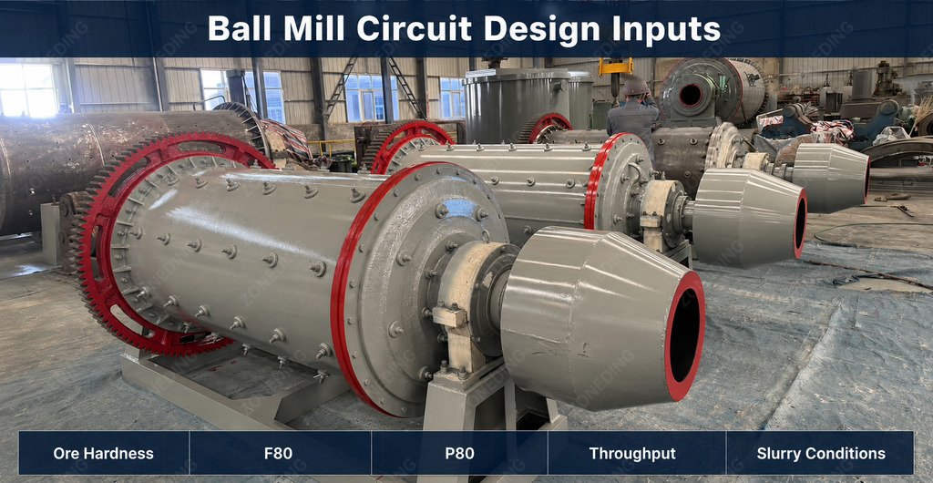
Ball mill circuit design inputs including ore hardness F80 P80 throughput and slurry conditions
Design Input
Why It Matters
Ore type and mineralogy
Indicate liberation behavior and slurry characteristics
Ore hardness and grindability
Determine the energy needed for size reduction
Feed F80
Defines the incoming grinding duty more accurately than maximum feed size alone
Required throughput
Sets the fresh solids load and preliminary equipment duty
Target P80
Defines the required circuit product size
Slurry density and rheology
Affect pumping, mixing, and classification
Available process water
Influences density control and total hydraulic load
Downstream process
Determines the acceptable product size and slurry condition
Ore variability
Defines the operating range, not only the design point
A circuit designed around one easy-to-grind sample may become undersized when harder ore enters. A mill selected for one F80 can also lose capacity when upstream crushing delivers coarser feed.
Only then should the mill, cyclone cluster, sump, pump, piping, and water controls be finalized. For preliminary sizing, see how to calculate ball mill capacity.
How Do You Select a Hydrocyclone for the Required Product Size?
Hydrocyclone selection cannot be reduced to a rule such as:
One cyclone diameter equals one product size.
Classification depends on:
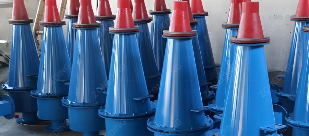
Hydrocyclone selection factors including pressure geometry slurry density and solids load
Cyclone diameter and internal geometry
Feed pressure
Feed flow rate
Feed solids concentration
Slurry density and viscosity
Apex or spigot size
Vortex finder dimensions
Feed particle-size distribution
Mineral density
Number of operating cyclones
A particularly important distinction is:
Target Product P80 ≠ Hydrocyclone Cut Size
P80 is the size through which 80% of product mass passes. A cyclone cut size, often expressed with a d50-type value, describes separation behavior. They are related but not interchangeable.
Because separation is imperfect, some fines reach the underflow and some coarse particles may enter the overflow. Select the cyclone for the combined duty:
Where throughput varies, a cluster can bring units online or offline to keep each cyclone in a suitable range. Check every geometry or operating change against overflow P80, underflow condition, circulating load, and throughput.
How Do You Calculate Circulating Load and Interpret the Result?
The ball mill receives two solids streams:
Ball mill circulating load calculation using fresh feed and hydrocyclone underflow
Fresh Feed + Cyclone Underflow
The returning underflow creates the circulating load. When dry-solids flow is measured directly, compare the amount returning in the cyclone underflow with the fresh dry feed entering the circuit. For example, if 60 t/h returns in the underflow while fresh feed is 30 t/h, the circulating load is 200%. The mill is therefore handling approximately 90 t/h of solids in total.
When stream tonnages are unavailable, a steady-state two-product balance can provide an estimate from representative cyclone-feed, overflow, and underflow samples. Measure the mass fraction passing the same sieve size in all three streams. Subtract the cyclone-feed passing percentage from the overflow value, then divide that result by the difference between the cyclone-feed and underflow values.
For example, if cyclone feed is 45% passing, overflow is 90% passing, and underflow is 15% passing, this method gives an estimated circulating load of 150%.
Use this estimate only when:
The circuit is steady during representative sampling
All values use the same sieve size and dry-mass basis
No unaccounted solids stream crosses the balance boundary
For a formal survey, use dry-solids flows and a reconciled mass balance. Density alone can mislead when slurry specific gravity or sampling quality is uncertain.
There is no universal best percentage. The acceptable load depends on ore hardness, mill power, F80, target P80, classification, pump capacity, and downstream requirements.
High circulating load is often a symptom rather than the root cause. Possible causes include insufficient grinding, coarser or harder feed, poor classification, fine bypass to the underflow, or unstable cyclone feed.
How Should the Sump, Pump, Water, and Cyclone Work Together?
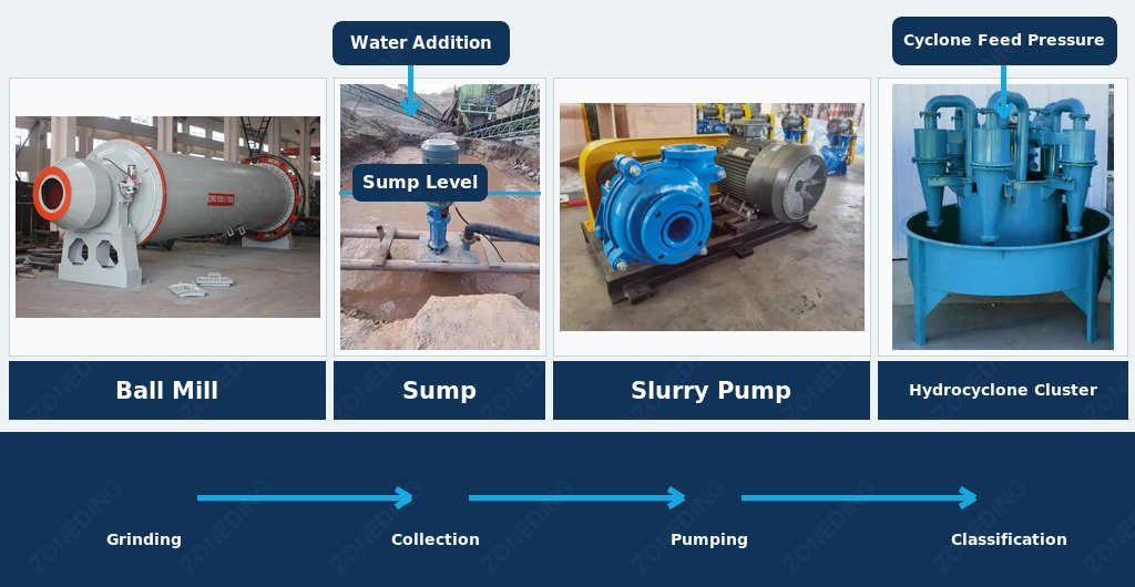
A real grinding circuit is not simply a ball mill connected to a cyclone. The intermediate equipment controls whether classification remains stable:
Ball Mill → Sump → Slurry Pump → Cyclone Cluster
The sump buffers mill-discharge changes. The pump supplies cyclone flow and pressure. Water addition affects density, viscosity, hydraulic load, and classification.
Ball mill sump slurry pump water control and hydrocyclone cluster system
Rapid sump-level changes cause pump and pressure fluctuations. Pump wear, air entrainment, blocked lines, density changes, or the wrong number of active cyclones can destabilize overflow even when cyclone bodies are sound.
Water is a control variable, but more water does not automatically improve classification.
Too much dilution increases the volume to pump and classify. Too little water may create high viscosity or poor transport. The target is stable density and flow for the specific ore and cyclone arrangement.
A useful relationship is: Stable Sump → Stable Pump → Stable Cyclone Feed → More Stable Classification
Before changing cyclone geometry, verify:
Sump level stability
Pump condition and speed
Cyclone feed pressure and flow
Slurry density and rheology
Water addition points
Number of operating cyclones
Pipe, valve, and manifold condition
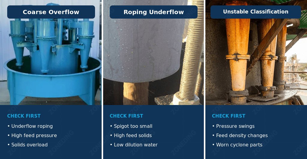
What Causes Coarse Overflow, Roping, and Unstable Classification?
Troubleshooting should begin with symptoms, samples, and operating measurements—not an immediate equipment change.
Hydrocyclone troubleshooting for coarse overflow roping and unstable classification
Symptom
Main Areas to Check
Why It Matters
Overflow becomes too coarse
Fresh-feed F80, mill discharge PSD, cyclone pressure and density
The cause may be grinding, classification, or both
Excessive fines return in underflow
Water split, bypass, geometry, feed PSD
Already-fine material may be repeatedly ground
Cyclone pressure fluctuates
Sump, pump, air entrainment, density
Changing feed conditions move the separation point
Underflow becomes rope-like
Solids loading, restriction, apex condition
Roping can increase coarse misplacement to overflow
Cyclone adjustment cannot create missing grinding energy
Overflow P80 varies
Feed variability, mill discharge, pump and cyclone stability
Product control requires the entire circuit to be checked
Roping is a visible warning, but its cause must be confirmed. Check pressure, solids concentration, solids load, spigot condition, blockage, pump performance, and sump behavior before changing the apex.
Coarse overflow does not automatically mean the hydrocyclone is at fault. If mill discharge is already coarse because the ore is harder, F80 has increased, or mill capacity is insufficient, classifier adjustment cannot supply missing breakage energy. If mill discharge remains acceptable but coarse material reaches the overflow, classification is the stronger suspect.
Online pressure, density, power, flow, and particle-size instruments can shorten the feedback cycle. Advanced control may coordinate feed rate, sump water, pump speed, and active cyclones. However, automation does not replace representative sampling, calibration, or a mass balance.
The operating target remains a balance:
A good ball mill–hydrocyclone circuit does not produce the finest possible overflow. It produces the required P80 at stable throughput, efficient classification, and acceptable energy consumption.
Frequently Asked Questions
What is the purpose of a hydrocyclone in a ball mill circuit?
The hydrocyclone classifies the ball mill discharge. A larger share of fine material leaves through the overflow, while a larger share of coarse material returns through the underflow for further grinding.
Does hydrocyclone overflow always go to flotation?
No. It often becomes flotation feed in concentrators, but it may also report to gravity separation, magnetic separation, leaching, thickening, or another stage. The flowsheet determines its destination.
What circulating load should a ball mill use?
There is no universal target. The suitable operating range depends on ore grindability, mill power, F80, target P80, classifier performance, pump and cyclone capacity, and downstream requirements.
What should I check when hydrocyclone underflow starts roping?
Check feed pressure, slurry density, solids load, apex condition, blockage, pump performance, and sump stability. Do not widen the apex before confirming the cause and measuring the effect on overflow P80 and circulating load.
How can I control hydrocyclone overflow P80?
Check both grinding and classification: ore hardness, fresh-feed F80, mill discharge PSD, mill power, cyclone feed pressure and density, water addition, cyclone geometry, active-cyclone count, and circulating load.
Key Takeaways
The ball mill performs grinding; the hydrocyclone performs classification.
The target P80 should come from liberation and downstream process requirements.
Product P80 and cyclone cut size are related but are not the same value.
Circulating load can be calculated from dry solids flow or estimated from a steady-state sieve balance.
There is no universal circulating-load, pressure, or slurry-density target for every ore and circuit.
High circulating load is often a symptom, not the root cause.
Sump, pump, water, pressure, and cyclone stability must be evaluated together.
Coarse overflow can result from insufficient grinding, poor classification, or both.
Optimization should begin with representative measurements and a circuit-wide baseline.
About ZONEDING
ZONEDING manufactures grinding, classification, flotation, and mineral-processing equipment for beneficiation circuits.
For a ball mill–hydrocyclone project, provide:
Ore type, mineralogy, and available test reports
Ore hardness or Bond Work Index, if available
Maximum feed size and F80
Required capacity in TPH or TPD
Target P80 and downstream process
Slurry characteristics and available water
Existing equipment and operating data for an upgrade
Site layout, power supply, and project location
These inputs allow the ball mill, sump, slurry pump, hydrocyclone cluster, water system, and downstream process to be evaluated as one connected circuit rather than as separate machines.
Operating heavy mining equipment requires a deep understanding of internal mechanics. Many expensive machine failures happen because operators misunderstand basic operational rules. Good equipment can break quickly when handled poorly. This compre...
A rod mill working principle differs from other grinding tools because it uses long steel rods instead of balls. This machine is the best choice for preventing "over-grinding," which ruins fragile minerals. Many plants lose profit becaus...
We use cookies to ensure that we give you the best experience on our website. If you continue to use this site we will assume that you are happy with it.
Privacy Policy
Send us a message
We would love to hear from you
Submit your question and our team will respond to the email provided as soon as possible.
 Zoneding Machine